Extending Energy Storage Life in IoT
Author: Ed Spence
1/23/2023
Abstract
A discussion of energy storage attributes beneficial to IoT applications, with use cases.
Introduction
There is extensive literature available regarding the use of batteries and other energy storage devices, most focused on large energy storage for EVs and backup power applications. Relatively little is written about selection of energy storage for IoT applications, or technologies and methods to maximize the life of energy storage to power wireless sensors.
This article will focus on the use of rechargeable energy storage technologies to improve the operating lifetime of wireless sensors. In particular, we will discuss the characteristics of high Cycle Life technologies such as Supercapacitors, Hybrid Supercapacitors and a lithium based battery technology, Lithium Titanate Oxide (or LTO), with use cases where and how these technologies can be used to boost sensor operational life.
Practical Comparison of High Cycle Life Energy Storage Technologies
Selecting and designing energy storage into an IoT device adds several layers of complexity to required lifetime or duration estimations and hence, technology selection. For example, wireless sensor operation with periodic measurement and transmission cycles that require relatively short bursts of energy can adversely impact battery storage capacity.
In addition, how frequently the energy is required, and over what time duration, will favor one type of energy storage technology over another, each with different energy delivery profiles.
The energy storage characteristics of interest to wireless sensor designs include:
- High efficiency charge / discharge with less internally generated heat (safety), with simpler, lower cost Battery Management Systems (BMS).
- Ability to deliver high amounts of energy to the load over a short time duration (power) repeatedly, e.g. current impulse during radio transmission, without negatively impacting long term capacity.
- Low self-discharge (leakage), which robs the energy storage of its ability to deliver the rated capacity.
- High cycle life and charge current levels supportive of using Energy Harvesting (EH) as primary or supplemental source of energy.
Supercapacitors store large amounts of charge electro-statically, such that when discharged the voltage drops steadily relative to the load. Rather than supply steady energy to a circuit with a relatively constant voltage as a battery does, the Supercapacitor can deliver power within a very short time duration, depending on the load. Note also that Supercapacitor datasheets describe the energy capacity in terms related to the physics of capacitance, such as Equivalent Series Resistance (ESR) and drop in capacitance, rather than the mAh capacity specified for batteries2.
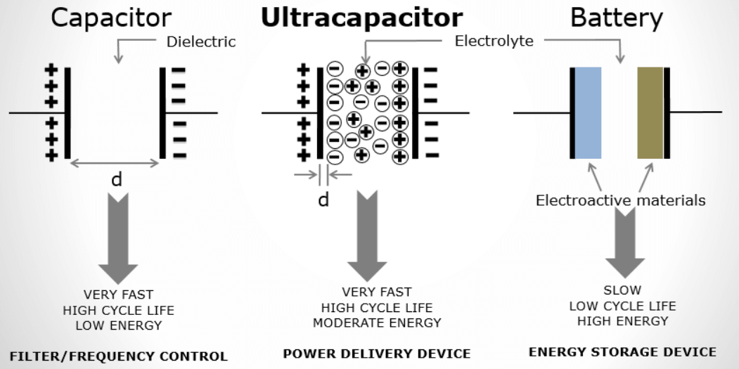.png "ultracapacitor-(1).png")
Figure 1. The fundamental difference between capacitive (electrostatic), battery (chemical), and Supercapacitive charge storage. Image credit: Cornell Dubilier.
An alternative technology option, so called ‘Hybrid Supercapacitors’ (also known as Li-Ion Capacitors) are designed to merge the energy capacity capabilities of chemical battery technologies with the high power delivery of dielectric capacitors in one compact package. These technologies combine charge time (minutes), cycle life (100k’s) and self-discharge performance of EDLC with higher energy storage capacity. As capacitors, they are typically not constrained by any shipping restrictions.
One more technology variation has been the development of small capacity, Lithium Titanate Oxide (LTO) batteries. As a battery technology, LTO provides higher capacities per weight or volume than EDLC Supercapacitors while retaining the ability to deliver higher power to a load in a short time along with a high charge/discharge cycle life. That said, currently available LTO batteries are available with lower capacities (energy densities) than other Lithium-based batteries3 applicable to portable applications.
A graphic describing the energy delivery capability of the three technologies is shown in Figure 2.
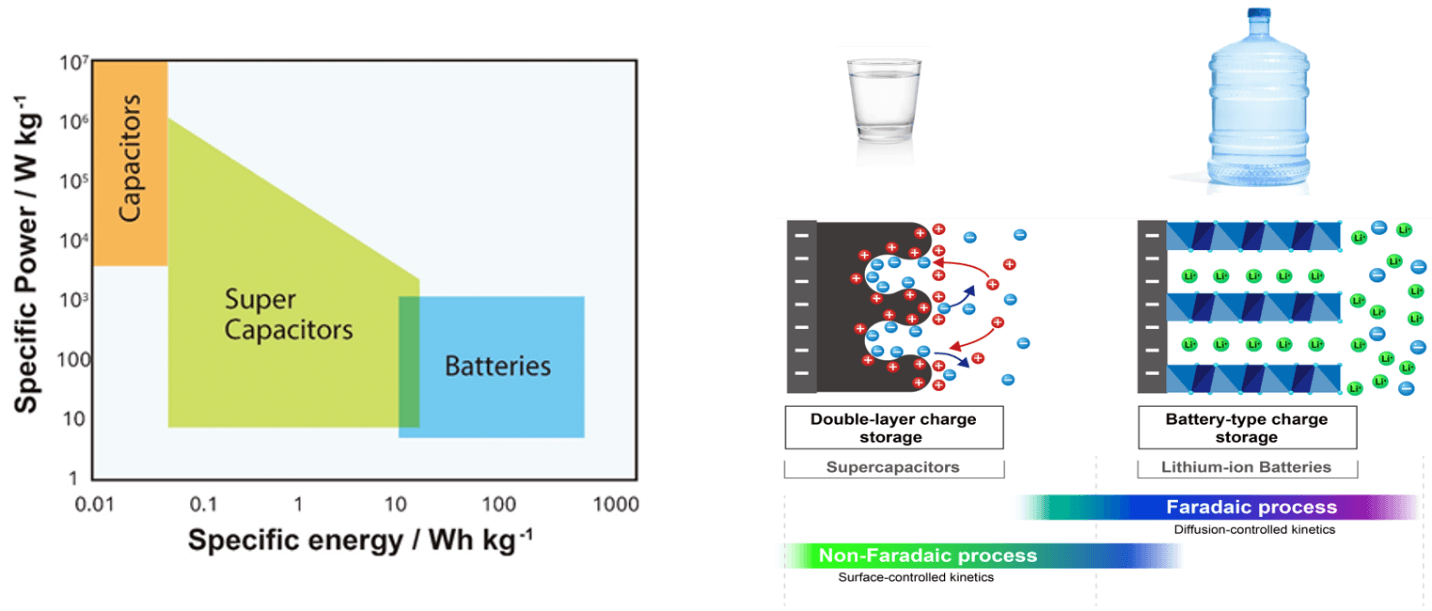.png "energy-density-correlation-(1).png")
Figure 2. Correlation of energy density and power density. Image courtesy of Nichicon Corporation.
Typical IoT Functionality and Relevant Energy Storage Characteristics
A functional block diagram for a wireless sensor device typically consists of sensor signal capture and digitization (if the sensor is not integrated into the enclosure), radio controller, energy source, power management, memory, clock (crystal) and microcontroller for operational control and any embedded signal processing. A typical functional diagram is shown in Figure 34.

Figure 3. Functional block diagram for typical wireless sensor.
For any electronic design, energy needs start with a detailed estimation of the power budget consistent with design goals. The overall design of the sensor function is driven in turn by the application, requiring several architectural choices that will impact the overall power budget.- What measurements are required, and what is the optimum sensor technology to ensure measurements are made with sufficient accuracy and resolution?
- How often do measurements have to be made, and what are the time durations of various levels of sleep, wake up, measurement and transmission?
- What is the desired duration of the device operation in the field before battery change (or recharge) is required?
- If rechargeable energy storage, from what source? (e.g. energy harvesting).
- How efficiently does the radio and protocol chosen for the application reliably establish and maintain connection when required?
IoT Power Budget and Capacity
With these decisions made, appropriate components can be selected to accomplish their respective tasks with an eye toward minimizing power consumption. Current consumption for each function can be estimated from datasheet specifications and associated with the various operating states of the wireless device. Since energy storage devices such as batteries are rated for their capacity to deliver current to a load, power budgets typically calculate charge consumed by integrating the current drawn over a period of time, yielding charge consumed for each operating state in units of A-s. The total charge over a complete cycle can then be summed over a given time period and used to estimate battery life for an estimated battery capacity5.
Typical operating modes include:
- Data acquisition (DAQ) wake up
- Measurement and digitizing
- Data formatting for transmission and radio wake up
- Transmission connection established
- Data transmission
- Shutdown
Ed Kuzemchak, CTO of Software Design Solutions, suggests a good place to start estimation of the power budget for any design is a spreadsheet with key components of the BOM, “Never underestimate the value of a ‘battery estimator’ spreadsheet that outlines all the modes of the system (sleeping, waking, sampling, processing, sending). And then measure the power of each of those activities, citing the percentage of time each of those elements take up in the overall measurement and transmission cycle. This has been very useful in analyzing what to optimize.
A power hungry sensor that you hardly ever access may not be worth swapping out. A mode that is only 2% of your run time and 5% of your energy may not be worth optimizing. Maybe sleep power is 50% of your draw? Hard to tell until you run the numbers. A simple spreadsheet model, as a first estimate, can be very useful in telling you where to focus your design efforts to reduce power consumption, and when you have reached diminishing returns.”

Figure 4. A preliminary power budget for a prototype 500C surface temperature sensor using BLE protocol. Courtesy Software Design Solutions Inc.
Each operating state takes a finite amount of time, including ramp up/down, and is highly dependent on configurable variables for each functional block. Radio modules are very complex SoCs, with many details configurable (such as packet size, transmit bandwidth and power, desired bit rate and acceptable error rate). Radio module vendors provide simulation tools to estimate ‘time-on-air’ transmission time with selected operating factors determined by the designer as required for the application. Tools such as this can improve accuracy of the estimate.
Once operating parameters such as measurement interval, with associated charge consumption for each cycle, is determined, we can add an estimate of total sleep mode charge. Typically, the total charge per cycle and the desired number of cycles yields an estimate of the required energy to achieve operation for a desired period of time, and is taken as a starting point for selection of battery capacity, but other factors impacting rated capacity must also be considered.

Figure 5. ‘Time on Air’ simulation tool for a LoRa radio chip, the Semtech SX1280. Image credit: Semtech.

Figure 6. Idealized estimate of integrated current consumption for a LoRa radio transmission. Image credit: Semtech6.
Consulting the published family of battery capacity curves from any datasheet, we can see that battery capacity is highly dependent on not only average current but also operating temperature. It’s clear from the chart in Figure 7 that battery capacity is not a static figure of merit.
There are other figures of merit that vary by battery technology, such that the literature suggests that one battery technology or another may be a better fit for certain applications, such as storing charge from a 12 V PV cell with frequency charge/discharge cycles. Cycle Life, Depth-of-Discharge (DOD), self-discharge are all characteristics of battery behavior that also impact the actual lifetime.

Figure 7. Battery discharge characteristics determine the battery life. Operating life for a specific battery model will vary with the average current consumed by the application. Battery capacity is also highly dependent on operating temperature, note that this family of curves holds temperature constant. (Image credit: Tadiran).
Application specific discharge characteristics such as high current impulses common to wireless sensor designs, for example, may also impact battery state of charge.
We will discuss these issues further, but for now it must be understood that capacity is not a fixed metric for battery performance, but must be estimated by factoring in multiple variables related to operating conditions, energy storage technology and the application, or tested with specialty equipment for the purpose.
Power versus Energy Delivery
As an example, we illustrate the current consumption characteristics of a wireless temperature sensor using a BLE radio. The BLE radio (server) is operating in an ‘Advertise’ mode, where three pulses are periodically transmitted to any listening device in range. A mobile (client) notifies the wireless sensor that it wants to connect and receive a data packet. Measurement of the current draw profile as measured at the battery for this exchange looks as shown in Figure 8. Note the high current draw (mA’s) over a short time period (ms’s).

Figure 8. The measured current drawn from the battery during sleep, advertise and connect modes of a BLE temperature sensor. The vertical axis is in A’s of current. Source: The Machine Instrumentation Group.
Repeated, high current discharge may contribute to degradation of battery capacity over time. Studies have discussed degraded capacity or number of discharge cycles under various conditions including temperature, DOD and elevated discharge rate (C)7, due to complex chemical interactions that increase internal resistance.
Rapid discharge (or charge) can result in an unwelcome increase in temperature within the battery enclosure, particularly in Lithium based battery chemistries, damaging or impairing the capacity8. This problem historically occurred when older Lithium batteries were charged with high current to shorten the charge time, then overcharged. Safer lithium ion chemistries are used today for the cathode (e.g. Cobalt, Manganese, Nickel, or Iron Phosphate), with more sophisticated battery charge controller circuitry to prevent these problems, with some sacrifice in energy density (capacity per physical volume or weight).
For more demanding IoT applications, such as vibration measurement for industrial Condition Monitoring, the short term charge output for each measurement and transmission cycle may be significantly longer than for simple environmental sensors sampling scalar values such as temperature, barometric pressure and relative humidity (RH), with associated impact on long term battery performance. The radio protocol, transmission distances and transmission efficiency will also contribute to the required transmission power.Standby Current and Energy Storage Self-discharge
Let’s assume that we wish to take a measurement and transmit once per hour with the BLE temperature sensor mentioned previously. The total charge consumed during a transmission cycle was 86 µA-s, excluding sleep current. The transmit duty cycle for an hourly data transmission is 0.0000024%, which means at this measurement interval, the sleep current dominates the energy consumption. In this case the designer skill at reducing residual leakages while maximizing operational efficiency of the various functional blocks is the dominant design factor in maximizing battery life9.
However, as the frequency of measurements and transmission increases, the higher radio transmit power asserts itself and reduces the expected battery life.

Figure 9. Although Sleep mode can dominate the power budget in this BLE example when operating with low measurement intervals, the BLE radio transmit power rapidly asserts itself as the frequency of measurement increases. Source: The Machine Instrumentation Group.
The impact that circuit leakage drawing charge 24/7 has on battery life applies to energy storage self-discharge as well. To maximize device operating duration while minimizing required capacity cost and physical battery size, both behaviors might be considered in the power budget estimates due to the degraded capacity over time. Self-discharge rates for various energy storage chemistries can be as high as 30% monthly (Nickel based chemistries), to less than 5% for lithium based batteries, and LTO battery technologies10. Furthermore, supercapacitors have higher self-discharge rates than batteries.

Table 1. Relative self-discharge rates for available energy storage technologies.

Figure 10. The self-discharge curves of a Supercapacitor. The capacitive technology starts to lose it’s charge when disconnected from a charging source due to the high internal resistance. Note the ability to hold a charge degrades with elevated temperature. Source: Kemet.
Cycle Life and Depth-of-Discharge
Some IoT applications are in a position to take advantage of power sources to recharge or maintain an SOC level of the energy storage device, whether from battery removal and recharge, wired power availability or access to renewable sources via energy harvesting technologies.
If the application provides for recharge of the energy storage device, then additional energy storage criteria must be considered when selecting the technology.
- How much time (or current) is available to charge the device?
- How often will a charge / discharge cycle be required?
- How deeply will the device be discharged for every cycle (Depth of Discharge, or DOD)?
- How many cycles are desirable over the life of the application?
For many battery chemistries, the lower the discharge current, the higher the effective capacity (e.g. longer operating life). When charging, the higher charge rate, the shorter the charge time but with a negative impact on longer term available battery capacity. Figure 10 shows the impact on capacity for various charge rates11 for an LTO battery technology.

Figure 11. Charge and discharge characteristics as a function charge current, traditionally specified as a % of capacity, C. This family of curves is for a lower capacity LTO device which is capable of high charge / discharge currents. Image courtesy of Nichicon Corporation.
Cycle Life is typically defined as the number of charge/discharge cycles performed before the capacity is reduced to 80% of nominal. Depth-of-Discharge (DOD)12 is also cited as a necessary condition for this specification. Caution must be taken interpreting this specification as Cycle Life varies greatly with DOD, see Figure 12 for an example.
A comparison of the cycle life specifications for a selection of energy storage products are tabulated in Table 2.

Figure 12. Cycle life as a function of Depth-of-Discharge, or DOD, showing the impact of discharge depth on Cycle Life as a proxy for lifetime capacity. Source: Panasonic VL3032 rechargeable Li-MnO2 coin cell datasheet.

Table 2. A selection of small to medium capacity energy storage devices.
As can be seen from the table, Hybrid Supercapacitor and LTO technologies have a very high Cycle Life, much like EDLCs, but are capable of higher energy storage capacity13 and can handle much higher max continuous currents than other lithium technologies.
Other Considerations for Battery Selection
Additional factors related to the application must also be considered, and include:
- Physical dimensions of the device and the mechanical volume allowable for energy storage (with mounting and contact frame).
- Expected operating temperature range.
- The lowest voltage at which the IoT device circuitry can operate and the cut-off voltage of the battery, which will signal the end of the operational life of the device.
- Overall cost of ownership.
Since most IoT applications almost by definition seek to minimize maintenance (battery replacement or removal for charging) due to the manual labor involved, we are concerned with the impact of all these variables to the longevity (long term capacity) of the energy storage device.
Application
Combining Battery Technologies
With such a variety of energy storage devices available with fundamentally different energy delivery characteristics, it should come as no surprise that efforts are made to combine the best of all technologies. Several energy storage technology vendors offer products that electrically and mechanically combine both a higher energy density battery with a higher power-density Supercapacitor, Hybrid Supercapacitor or even LTO battery technology. With high cycle life and high discharge current capability, these companion technologies more efficiently and quickly provide momentary power necessary for measurement and wireless transmission.
Capacitors applied in this way effectively smooth out the load on a battery by filtering voltage changes due to load current impulses, effectively reducing the source impedance seen by the load. Supercapacitors do the same thing only better, with much lower ESR and much higher energy density than traditional capacitors14. This auxiliary power capacity source must necessarily have high Cycle Time, or ability to charge / discharge large amounts of charge frequently without diminishing capacity. In addition, a high Depth-of-Discharge (DOD) capacity is also very beneficial, enabling maximum power delivery cycle after cycle.
Figure 13 shows the energy consumption profile of a high performance vibration sensor transmitting full waveform data via Wi-Fi. Positioned to connect anywhere Wi-Fi is available, this protocol designed for LAN applications delivers very high data rates but is also very demanding in terms of power.

Figure 13. The current consumption profile of a vibration sensor transmitting data via Wi-Fi. The total transmission charge is 1.387 A-s, integration time 12.4 s. Source: The Machine Instrumentation Group.
The designer of this device opted to provide both energy and power via a combination battery product, shown in Figure 14. The large capacity D size Lithium thionyl Chloride cell specifies nominal capacity of 19 Ah with 5 mA average current at 20 C. Although specified as capable of providing a pulsed current max of 400 mA, it is unlikely the nominal capacity would always be available in this application with such frequent high current impulses, hence the design choice of coupling the lithium cell with a 100 F, 4.0 V Supercapacitor to provide the high current impulses prevalent in the Wi-Fi signal. Supercapacitor technology can deliver Amps of current in a short period due to very low ESR (Equivalent Series Resistance), current levels that can damage or even lead to safety concerns for a lithium battery.

Figure 14. The energy storage battery combination used in a vibration condition monitoring sensor, providing the capability to transmit via both WIFI and Cellular. Source: The Machine Instrumentation Group.
A capacitor-based energy storage technology should extend the primary cell life by enhancing efficiency of the chemistry-based energy exchange since the battery now recharges the high capacity of the Supercapacitor, stored to be delivered from the cap instead during high demand. Unlike chemical energy storage options, capacitive based technologies have very high (virtually unlimited) Cycle Life, or the ability to fully charge and discharge with minimal impact on overall capacity for power storage and delivery. Supercapacitors and Hybrid Supercapacitors boast a Cycle Life of 500k or higher, while specialized battery technologies such as LTO provide higher amounts of energy storage while specifying cycle life of 20k or higher.

Figure 15. Depth-of-Discharge (DOD) or capacity retention versus the number of cycles for a 150 mAh LTO battery. Cycle Life is typically specified as the number of 100% DOD cycles executed before capacity falls to 80% of nominal. The LTO technology delivers a much higher cycle life than Li-Ion based batteries (typical 2,000 to 4,000 cycles) but less than EDLC. Courtesy Nichicon Corporation.
Ed Kuzemchak notes: “We have long included a Supercap in all of our IoT designs as a matter of habit, believing that we are extending Lithium Ion battery life by using the cap to provide the necessary current during sensor measurement and transmission. We believe that the additional expense and leakage of the Cap are outweighed by the extended battery life, though admittedly it is very difficult to quantify this. The newer light capacity LTO batteries are very intriguing, as it provides more energy density than an EDLC, and has less self-discharge. Cycle Life of 25,000 is more than sufficient for most of our applications to date. It would be interesting to see some empirical comparisons...”15.

Figure 16. Experimental measurements showing runtimes of a 2A GSM load on a 3.6 V 600 mAh Li-ion battery. The grey trace shows battery voltage without a Supercapacitor in parallel, while the black trace uses a 380 mF, 80mΩ Supercapacitor. Source: cap-XX16.
Power (Battery) Management
Power management circuit complexity depends on the battery technology, whether it is rechargeable, and whether Supercapacitors are involved in the energy delivery or not.
In general, the first consideration are the power supplies required by the circuits in the IoT design.
Ed Kuzemchak explains “Most hardware systems require a stable voltage that is not the exact 1.5, 2.4 or 3.6 volts provided by the battery cells. Power regulation circuitry is employed to provide a stable voltage as the battery voltage drops during discharge. A hardware system may require multiple 'voltage rails' for various components that require for example 5 V, 3.3 V, 1.8 V and 1.2 V in the same system.
It is important to consider the efficiencies of the power regulation in the calculation of overall power profile of the system, and the subsequent battery life. Power regulation is a whole field of study, but put simply, there will always be some amount of loss during power regulation. More sophisticated regulation circuits can reduce the loss at the expense of additional components and BOM cost. It is best to model all the various voltage rails in a hardware system separately and optimize those with the largest benefit.
Next consideration is the operation states programmed into the device firmware, subject to the capabilities of the wireless controller and very dependent on the application.”
These observations apply to all energy storage technologies but the situation can become considerably more complicated with rechargeable energy storage technology.
Li-ion batteries must be charged with an intelligent Battery Management System for safety purposes, as overcharge can damage the battery due to excessive heat generated, in some cases creating a safety hazard. A cell charge is begun with a constant current, transitioning to a constant voltage as SOC (State of Charge) nears 100% (CCCV). Since SOC can be difficult to measure or estimate, charge mode transitions are often managed by programming voltage thresholds corresponding to the charging stages. These voltage setpoints will differ by type of battery, see Figure 17 for a charge profile typical of a Lithium battery.

Figure 17. Typical charge cycles for lithium battery technology. Image credit: Battery University17.
We would be remiss if we didn’t mention that LTO is a lithium based technology that does not necessarily require this level of BMS sophistication in order to charge quickly and safely when compared to other lithium technologies.
According to Tom Bando, Director of Solution Sales at Torex Semiconductor, a simple LDO based circuit providing a constant voltage suffices in most cases.
“The LTO batteries that we have experience with will charge safely with constant voltage and just need a specific CV level. In our experience, many applications utilizing low capacity batteries such as LTO are usually size constrained or have cost sensitivity, or need other performance characteristics provided by this technology. A simple LDO with low Iq, small package options and customized output voltage level are a good solution for designers looking for a simple charging solution.”

Figure 18. Example LDO based power management circuit for charging LTO battery technology. Source: Torex18
Use Cases
Wireless Temperature Sensor with Photovoltaic EH
Let’s again consider the BLE temperature sensor discussed earlier. Guidance from vendor specifications regarding the ½ A 1,200 mAh Lithium Thionyl Chloride battery life ($6 in 100’s) suggests 30 days continuous operation with very frequent measurements and transmissions.
What can be done to improve the performance of this design?
For an application operating outdoors, such as an agricultural setting with reasonable amounts of annual sunshine, we can also consider adding a small, low cost photovoltaic (PV) panel externally to the sensor. A small size solar panel (30 cm x 30 cm) can provide 10’s to 100’s of mA’s of current to charge an energy storage cell. As discussed, charging a chemical storage cell takes time, such that when considering limited charge time when sunshine is available, we might choose technology with faster charge times such as a Supercapacitor in parallel with a modest capacity battery such as an LTO cell.

Figure 19. This smart bike lock uses small, flexible photovoltaic panels along with high Cycle Life LTO rechargeable batteries to extend IoT device operation almost indefinitely. A cellular radio provides tampering information and location. Courtesy PowerFilm Corporation.
An LTO, which unlike a capacitor, can store energy chemically while still charging with a high current (up to 20 C), a charge might occur in a matter of minutes with the output current of a PV panel. With additional capacity from an LTO battery the IoT device might transmit indefinitely when augmented by any available sunshine in that 30 day period! The chart in Figure 20 shows how quickly an LTO cell could be charged, based on the available charge current.

Figure 20. The charge time of a 150 mAh LTO battery, as a function of charge current. Note that 1C is equivalent to 150 mA. Courtesy Nichicon Corporation.
An additional benefit to both Hybrid Supercapacitor and LTO battery technology is the low self-discharge. Many energy storage technologies exhibit low internal resistance such that the EH technology effectiveness is diminished by having to replenish this lost energy capacity also.
Dan Stieler, President of PowerFilm Corporation, provider of flexible, custom made photovoltaic cells has been working with LTO battery technology for this reason. He believes that the cost of ownership of the PV technology coupled with the low leakage, high Cycle Life LTO technology reduces the cost differential over time when compared to other lithium based batteries with higher capacity. “For large deployments, the cost of manual battery replacement over time eats into the initial cost savings of a non-rechargeable or low Cycle Life rechargeable battery technology. LTO can completely charge and discharge 10’s of thousands of cycles, compared to a few thousand for other lithium batteries. This has to be considered as part of the total cost of ownership of the IoT system.”
Asset Monitoring and LTE Transmitted Alarm with Backup Battery
Many mission critical applications will use an alarm transmission mechanism apart from the wireless transfer of data. In this example application, an LTE module is designed for signaling asset condition or status. The LTE module is used to monitor the temperature, electric power consumption, and other conditions of various devices. The module periodically transmits the device status (energy consumption) to the cloud. LTE-CAT M1 was selected for WW operation, and requires high power for communication. An energy storage device with enough capacity to power the transmission, in this case a 150 mAh LTO battery product is used. The integrated energy storage of the LTO device enables communications independent of the device's main power circuit, such that device status can be monitored even when the main power is interrupted.

Figure 21. This LTE-CAT M1 module is used to monitor the temperature, electric power consumption, and other conditions of various devices. The module periodically transmits the device status (energy consumption) to the cloud. Courtesy of Nichicon Corporation.
Extending Low Temperature Operation
Various battery technologies suffer from limited ability to deliver a charge and discharge at low temperatures. LTO (Lithium Titanate Oxide) technology offers better charge delivery performance than other lithium based technologies down to -30 °C, making this technology a useful partner to a larger capacity battery to extend effective temperature range for short periods.

Figure 22. The low temperature discharge capacity performance of Nichicon SLB series. Courtesy Nichicon Corporation.
Summary
Development of high Cycle Life energy storage technologies enables design of energy sources with characteristics that extend the operational duration of IoT devices. Supercapacitors and LTO technology in particular perform well against other lithium based batteries in terms of Cycle Life, Depth of Discharge, leakage current, safe operation and low temperature performance, enabling the IoT designer flexibility to configure an energy source to extend operational lifetime of low power, portable applications.
About the Author

Ed Spence is the Founder and Managing Director of The Machine Instrumentation Group, a collaborative network of contract engineering service providers with an available pool of over 150 hardware, software and mechanical engineers.
Our broad array of technical competencies includes a deep working knowledge of machine health which includes IoT system and software development, vibration sensor technology and design, vibration measurement and signal processing, and data engineering for predictive maintenance.
1 Reference this article at FutureBridge for a readable review of Supercapacitor technology and application.
2 Some hybrid supercapacitor datasheets cite ‘stored energy’ in mWh, using formulas based on rated voltage versus minimum voltage.
3 We make this statement with several caveats to the capacity comparison, such as the lower LTO self discharge, and higher cycle life when compared to other lithium batteries. This comparison needs further examination.
4 “SoC issues for RF smart dust”, Cook et al, Proceedings of the IEEE, July 2006.
5 Actual realized battery capacity, generally specified for a nominal condition, varies greatly with application, operating conditions and time. These influences to be discussed further.
6 Application Note: Using the SX1280/SX1281 in Low Power Applications, August 2018
7 “Degradation of Commercial Lithium-Ion Cells as a Function of Chemistry and Cycling Conditions”, Y. Preger et al 2020 J. Electrochem. Soc. 167 120532
8 “Effect of High-Rate Cycle Aging and Over-Discharge on NCM811 (LiNi0.8Co0.1Mn0.1O2) Batteries”, Yin et al, MDPI Energies Journal, April 2022
9 Note that sleep mode current draw is also the most difficult operational state to measure accurately, due to the very low currents, requiring high resolution instrumentation.
10 Credible figures are hard to come by – product datasheets do not generally cite Self-discharge.
11 Commonly expressed as multiples of nominal capacity, or C.
12 DOD is expressed as a % of nominal capacity.
13 Energy density for capacitors depends on the loaded voltage at that moment, so can be cited as mWh for a given voltage. Since this is often changing in actual use, capacitors traditionally specify their electrostatic capacity in Farads (F).
14 Using Supercapacitors to Improve Battery Performance, Smith et al, IEEE Annual Power Electronics Specialists Conference, February 2002
15 Hybrid Supercapacitor and LTO technologies are typically an order of magnitude lower leakage than EDLC, hence the increased cost and physical volume required may be partially offset by a reduction in the lithium based battery capacity otherwise required to support operational life targets. In addition, DOD tends to be higher in EDLC and LTO when compared to lithium, hence less loss of capacity over many cycles. These effects are application dependent. More work can be done to better understand and even quantify these effects.
16 “Using Supercapacitors to Improve Battery Performance”, P. Mars, IEEE Annual Power Electronics Specialists Conference · February 2002
17 See BU-409: “Charging Lithium-ion”, for more discussion of charge and discharge of Li-Ion packs.
18 Applications and Solutions for Industrial/IoT, Torex Semiconductor Ltd.