Electrolytic Capacitors Replacing MLCCs
Author: Mark Gebbia
9/19/2018
The demand for components in modern day electronics has never been greater. Even with increased production capabilities component suppliers cannot keep up with demand. This has forced designers to find alternatives to their preferred components. This is especially true for ceramic capacitors. Designers are exploring the use of aluminum electrolytic and polymer (hybrids included) capacitors as alternatives to ceramic capacitors.
As shown below Aluminum electrolytic and conductive polymer electrolytic capacitors have some capacitance and voltage ranges that overlap making substituting an electrolytic capacitor for a ceramic capacitor possible.
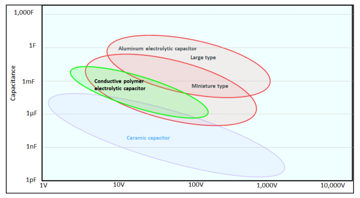.png "Screenshot_24-(1).png")
Since the behaviors of aluminum electrolytic and polymer electrolytic capacitors are different compared to the behavior of ceramic capacitors, designers must evaluate the differences and determine if those differences will have a negative impact on their designs and how much will their designs need to be altered.
These differences include:
- Capacitance – Aluminum and polymer electrolytic capacitors have capacitances starting at 1 μF and go as high as 10,000 μF in a single SMD case. Ceramic capacitors on the other hand have capacitances starting in the picofarad range and go up to several hundred microfarads in a single package. For capacitances below 1 uF ceramic capacitors are a designer’s main choice. Since Aluminum electrolytics and conductive polymers have larger capacitances in a single case a single Aluminum electrolytic or conductive polymer capacitor can be used to replace several MLCC capacitors saving board space.

- Dimension — Surface mount ceramic capacitors are commonly produced in a small rectangular shape. SMD electrolytic capacitors typically have their mounting bases in a square shape. Unless there is open space on the circuit board, changing from MLCC to electrolytics would require a redesign of the land pattern to accommodate the different shape of the capacitors. Several of the ceramic case sizes (0805 and under) are so small there are no electrolytic case sizes that are reasonably close to these parts so the designer cannot substitute electrolytics for those parts.
CASE CODE
Inch/
(mm)Base Dimensions
LxW
(Inch/mm)LYTIC, POLYMER
DIAMETER
(mm)LYTIC, POLYMER
LAND
PATTERN
(mm)CASE CODE
(mm)CASE CODE
Inch/(mm)Base
Dimensions
LxW
(Inch/mm)LYTIC, POLYMER
LAND
PATTERN
(mm)0603 .063x.032
(1.6x0.8)N/A N/A 2520 .25x.2
(6.35x5.05)6.3 6.6x6.6 0805 .079x.049
(2.0x1.25)N/A N/A 3530 .35x.3
(8.38x8.38)8 8.3x8.3 1206 .126x.063
(3.2x1.6)4 4.3x4.3 4040 .4x.4
(10.2x10.2)10 10.3x10.3 1210 .126x.098
(3.2x2.5)4 4.3x4.3 4540 .45x.4
(11.4x10.2)12.5 12.7x12.7 1812 .177x.126
(4.5x3.2)4,5 4.3x4.3, 5.3x5.3 6560 .65x.61
(16.5x15.2)16 16.2x16.2 2220 .224x.197
(5.7x5.0)5 5.3x5.3 7565 .75x.65
(19.1x16.5)18 18.2x18.2 
Ceramic case sizes 1206, and above, have body lengths very close to electrolytic capacitors diameters. This makes it possible for an electrolytic capacitor to be a substitute for the ceramic capacitor with only the width of the available space needing to be changed if necessary.
- Capacitor height – Ceramics have very low heights due to their multilayer construction. In applications where the height is not tightly restricted the “top hat” case style of electrolytics can be utilized. Case heights for electrolytics start at 3.95 mm and can go as high as 21.5 mm.
- Temperature range – Thanks to continual improvements in the electrolytes, electrolytic capacitors are now available with temperature ranges that match or exceed ceramic capacitors. A temperature range like that of an X7R ceramic capacitor having a temperature range of ‐55 °C to 125 °C can be matched by polymers and electrolytics. Electrolytics can also reach temperatures as high as 150 °C.
Standard
ElectrolyticStandard
ElectrolyticHigher
TemperatureHybrids and
PolymersUUB UCJ UCX (135 °C) GYA (125 °C) UWH UCZ UBC (150 °C) PCR (125 °C) ULT UCH PCX (125 °C) ULH UUE A temperature range of -40 °C to 105 °C is more common with electrolytics and should be considered as an option for applications where high temperature ratings are not necessary.
Standard
ElectrolyticLow
ImpedanceHybrid and
PolymersFPCap UWX (85 °C) UCD GYB RPS/RPA UWT (105 °C) UCL PCF RHS/RHA UWP (BI‐Polar) UCM PCJ RFS/RFA UUL UCV PCV RSL UCB UWF UCW - ESR – Ceramic capacitors have an advantage when it comes to ESR at higher frequencies. They can have ESR values that are significantly lower than electrolytics while aluminum polymers and aluminum polymer hybrid capacitors have values that are about 75% lower than electrolytics. In applications where low ESR is important aluminum polymer and aluminum polymer hybrid electrolytic capacitors would be the best alternative.
- Voltage – Voltage is not a problem as both ceramics and electrolytics have voltage ranges that are very similar. Electrolytic capacitors do have one advantage. Their capacitance is not dependent on the amount of voltage applied to them like it is with a ceramic capacitor.

- Ripple current – Electrolytic capacitors have higher ripple current ratings than comparable ceramic capacitors thanks to their larger case sizes which allows them to more easily dissipate any internally generated heat.
- Temperature characteristics – Aluminum electrolytic capacitors and aluminum polymer capacitors have much more consistent and uniform temperature characteristics compared to ceramic capacitors. Aluminum Polymer and aluminum polymer hybrid capacitors have nearly linear characteristics over their entire temperature range.
- Frequency range – Ceramic capacitors can be used up to frequencies reaching into the megahertz range. Aluminum electrolytic capacitors are limited to 100 kHz while aluminum polymers/ hybrid capacitors can be used up to 500 kHz.


- Moisture sensitivity – Aluminum electrolytic and aluminum polymer hybrid capacitors are not as sensitive to moisture compared to ceramic capacitors and as a result they do not have a moisture sensitivity rating. Care must be taken when considering standard aluminum polymer capacitors where high humidity is present as these parts can short when exposed to these types of environments.
- Tin‐whiskering – Just like moisture sensitivity aluminum electrolytic capacitors and aluminum polymer capacitors terminations are not prone to tin‐whiskering and do not have a tin‐whiskering rating.
- Failure mode – Electrolytic capacitors consistently fail as an open circuit. Ceramics can fail as a short or open circuit or have its capacitance change depending on the source of the failure.
- Space saving – In applications where multiple MLCC capacitors are needed a single aluminum electrolytic or aluminum polymer capacitor can be used. This saves board space allowing smaller circuit boards to be used and lowers mounting costs by reducing the number of parts needing to be placed onto the circuit board.
As you can see each type of capacitor has its pros and cons. A capacitor is not just a capacitor. The performance characteristics of each type of capacitor can vary significantly and these differences must be taken into consideration before designing these capacitors into any circuit or be used as a substitution or replacement part. The differences can have adverse effects on the systems outputs and performance.