Impedance, ESR and Xc
Author: Mark Gebbia
5/5/2017
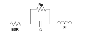
In textbooks, capacitors are treated as ideal lossless components. As a result, characteristics such as impedance and capacitive reactance are often considered the same, and the two terms are used interchangeably—and incorrectly. In the real world, capacitors are more complex. In fact, a real‐world capacitor is not just a capacitor. Internally, it is comprised of four basic characteristics:
- Capacitive (C)
- Resistive (ESR, or Equivalent Series Resistances)
- Rp (parallel resistance)
- Inductive (Xl)
(Rp (leakage current) is a DC component and will be included in this discussion.)
A simplified illustration of the equivalent real‐world capacitor is below.
.png "Screenshot_6-(1).png")
Where:
- Xc is the capacitive reactance= 1/ (2πfC) and measures the opposition of the capacitor to AC or pulse currents.
- ESR refers to the sum of all the resistances of the materials and internal connections within a capacitor.
Mathematically:
ESR=tanδ*Xc (Ohms) where tanδ or dissipation factor is the tangent of the loss angle.

Where:
- f=frequency in Hertz (Hz)
- C= capacitance
- Xl, or inductive reactance, is the sum of all the inductances of the materials and internal connections within a capacitor.
- Z, or impedance, is the total opposition to AC or pulse currents that flow through the capacitor.
Mathematically:
Z=
The frequency dependence of these characteristics is illustrated in the graph below.

There are several important characteristics that can be observed from the graph.
- The impedance makes a U or V shape that follows the XC and Xl characteristic lines.
- Xc decreases as frequency increases.
- Xl increases as frequency increases.
- ESR is very large at low frequencies, decreases very quickly as frequency increases, and continues to decrease at a much slower rate as frequency continues to increase.
As can be seen, the ESR and impedance are very close at low frequencies while at high frequencies they diverge.
There is another important point on the graph that deserves to be noted. Fr, or the self‐resonant frequency, is the frequency where Xc and Xl are equal. At this frequency, the impedance is equal to the ESR.
The behavior of the capacitors above this frequency is dominated by Xl. Since Xl is dominant, the capacitor acts like an inductor. Conversely, operation below Fr is dominated by Xc and the capacitor acts like a capacitor.
Fr is not a set frequency; it will change depending on the capacitance and dielectric type. For example, film capacitors can have an Fr in the megahertz/gigahertz range, while an aluminum electrolytic capacitor can have an Fr in the kilohertz range.
Mr. Gebbia is a 30-year veteran in the passive electronics industry. He is currently Sales Applications Engineering Manager at Nichicon (America) Corporation.