Low Voltage Energy Harvesting and Storage for Wireless Condition Monitoring
Author: Ed Spence
5/23/2024
Abstract
A discussion of potential for maintenance free sensor operation for wireless Condition Monitoring using photovoltaic energy harvesting with rechargeable energy storage technology.
Introduction
There is extensive literature regarding the use of high capacity rechargeable batteries as energy storage for EVs and backup power applications, and for 12 V rechargeable batteries for use with Solar cells. Less is written about application of rechargeable energy storage technology for wireless sensors (IoT). Applications more commonly discussed might be smart agriculture or smart city applications transmitting relatively low data content such as environmental conditions, remote control signals, UI data from PC peripherals and pricing data from electronic shelf labels. But what about more demanding industrial IIoT applications such as wireless Condition Monitoring?
As deployment of IIoT systems such as asset health monitoring accelerates, battery replacement as a cost of ownership is under increasing scrutiny. Despite this interest, there is still relatively little useful discussion of the operational life of the replaceable primary cell. While there is an expectation of continued improvement in primary cell battery life, the question is often asked – why don’t we see more energy harvesting (EH) technology used to reduce the cost of ownership for industrial IoT?
IIoT Cost of Ownership
In the drive toward the efficiencies of the digital factory, industry has increased the deployment of wireless Condition Monitoring to monitor the health of their assets, with increased visibility to the hidden cost of replacing batteries. Every consumer is familiar with the inconvenience of replacing the smoke alarm battery in the middle of the night, but what about the maintenance manager who has to keep 100’s of wireless sensors up and running in an industrial facility, many deployed in hazardous environments or locations that are difficult to reach?
“Our experience with short battery life has been costly,” says Tim Weilbaker, Vice President & General Manager of Allied Reliability’s Reliability Solutions group, a leading Predictive Maintenance services company. “With more than 20,000 wireless sensors of various brands deployed over the past five years, our data indicate that wireless sensor consumers should budget 8%-10% of the initial acquisition cost as an ongoing operating expense for the maintenance and upkeep of the wireless devices. About 90% of the ongoing maintenance costs are attributable to battery life not achieving expected longevity.”
IoT Operation and Energy Consumption
A wireless sensor will have several operational modes managed by the radio SoC (microcontroller), generally guided by the radio and protocol specific firmware. When not measuring, connecting or transmitting the device, the microcontroller will instruct all functions to enter a ‘sleep’ state.
IoT operation impacts the selection and effectiveness of energy storage in more than one way. For example, frequent relatively high current pulses associated with device power on or radio transmission may degrade some Li-Ion battery technology capacity over time.
For this reason when the load consists of a periodic high current period (measurement and transmission), designers often add an EDLC supercapacitor in parallel to the primary battery to deliver the power needed during transmission, which is then recharged by the primary battery cell during Sleep mode. The capacitor acts as a filter for the current surge, minimizing the sudden load on the primary energy source.
EDLCs have also been used as a back up energy storage element in an EH based system, to maintain operation for a limited period such as when the lights go out in the off shift. A newer energy storage option that has recently entered the market such as Lithium Titanate Oxide or LTO rechargeable battery technology offers capacities as high as 1,330 Joules (140 mAh) with high energy density (high storage capacity in a small form factor).
Example Industrial Application – Condition Monitoring
Vibration measurements often require long sample durations and hence higher energy data transmission. The host of RF interferers in a typical industrial environment as well as the cost of battery replacement have put the focus on long battery life, with the result that wireless Condition Monitoring sensors generally use larger capacity primary cell (non-rechargeable) batteries, with implications for cost of ownership (battery replacement), form factor, application (hazardous environments) and the environment. These factors make Condition Monitoring a particularly demanding wireless application in terms of energy consumption.
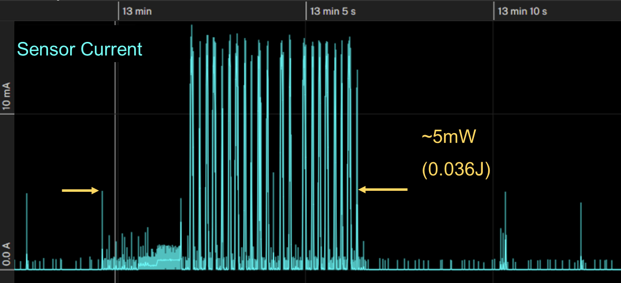
Figure 1. The current consumption profile of a wireless vibration sensor for Condition Monitoring applications provisioned with BLE 5.0. The average power during a typical 6.6 second transmission @ 25 °C and 10 m transmission distance can be 5 mW or higher. Once data transmission is complete, the radio SoC drops back into Sleep mode when not sending low power Advertise signals.
Photovoltaic Energy Harvesting
We were inspired by a smart bike lock product from Lattis Corporation that uses a flexible PV technology from PowerFilm corporation. The PV maintains a charge on an LTO battery in order to transmit location as well as tampering information via BLE to your mobile phone. Loss of power rendering the lock useless would be fatal to the product concept, hence an LTO battery is used as backup. A CNET reviewer cites eight years of continuous use, with an hour of sunlight sufficient to charge the small capacity battery for a week of operation.
.png)
Figure 2. This smart bike lock uses small, flexible photovoltaic panels with rechargeable LTO batteries to extend IoT device operation almost indefinitely. Courtesy PowerFilm Corporation.
PowerFilm makes custom flexible solar panels, and the standard product line includes both indoor and outdoor PV panels of various sizes.
Dan Stieler, President of PowerFilm Corporation, provider of flexible, custom-made photovoltaic cells believes that the cost of ownership of the PV technology coupled with the low leakage, high Cycle Life LTO technology reduces the cost differential over time when compared to other lithium based batteries with higher capacity. “For large deployments, the cost of manual battery replacement over time eats into the initial cost savings of a non-rechargeable or low Cycle Life rechargeable battery technology. LTO can completely charge and discharge tens of thousands of cycles, compared to a few thousand for other lithium batteries. This has to be considered as part of the total cost of ownership of the IoT system.”
Considering the breadth of PV options available, we explored use of PV technology with rechargeable energy storage for a wireless condition monitoring application in industrial settings. We need the rechargeable storage to enable operation for a period of time when the PV energy source is inactive as backup, such as indoor lights out during off shift or power outage.
Before further discussion of the evaluation system and component selection we’ll review some characteristics of available energy storage technologies that will help us interpret the test results.
High Cycle Life Rechargeable Energy Storage Technologies
Supercapacitors
Also known as Electric Double Layer Capacitors (EDLC), these capacitors store and deliver power due to very high capacitance (F’s) when compared to capacitors with ceramic or electrolytic dielectric. Capacitors traditionally serve as power supply by-pass in electronic circuits and in a similar way, EDLCs can be used to filter transient currents to minimize the voltage drop of a primary cell battery. For Lithium cells, this function can slow degradation of battery capacity due to consistently high load current transients. EDLC can also be used for auxiliary energy capture and storage, as a backup battery when using energy harvesting technology as the primary power source.
Like Li-Ion battery technology, as EDLC supercapacitors are discharged and recharged, the capacity will diminish over time. Lifetime is specified as the number of cycles at which capacitance is reduced by a percentage of its original capacity, typically 30% to 50% and specified over 250k to 500k cycles. EDLC capacity is also reduced at elevated temperature (as are batteries) and at increased charge voltages. EDLC are also cited as having very high self-discharge rates when compared with lithium based battery technologies1.
‘Hybrid’ Supercapacitors
Lithium Ion Capacitors (LIC) are hybrid supercapacitors that use a carbon-based material as the negative electrode which are doped with lithium, to enable charge storage. Like a conventional EDLC, they use activated carbon for the positive electrode.
LIC boasts lower self-discharge rates, higher maximum charge voltage and comparable charge/discharge cycle count to EDLC capacitors. However, like any battery technology (and unlike capacitors), LICs have a non-zero cutoff or minimum usable voltage, typically 2.2 V.
Lithium Titanate Oxide (LTO)
LTO is a recently introduced Lithium-based battery technology with high cycle life characteristics similar to LIC Supercapacitors. Some attractive features of LTO technology is the capability for high charge/discharge current, low self-discharge, low temperature operation (-30 °C) and low level charging current that could make it a good partner for energy harvesting (EH) technologies.
LTO technology delivers much higher charge/discharge cycles than other Li-Ion based batteries, up to 25k cycles with more than 80% capacity remaining (see Figure 10). For comparison, other Li-Ion battery technologies cite cycles of 1,000 to 5,000 before similar loss of capacity.
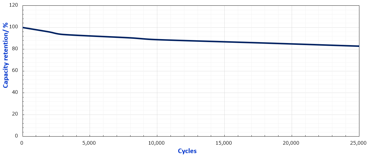
Figure 10. Depth-of-Discharge (DOD) or capacity retention versus the number of cycles for a 150 mAh LTO battery. Life Cycle is typically specified as the number of 100% DOD cycles (SOC 0% to 100%) executed before capacity falls to 80% of nominal. Source: Nichicon Corporation.
Figures of Merit for Energy Storage
Equivalent Energy Capacity
Since capacitors normally specify charge storage capacity in terms of Farads2, and batteries in terms of stored charge (mAh), we must equate the capacity of the two different technologies on the basis of stored energy. The equations for calculating stored energy for each type of technology are given below, where Vsto is the final or target voltage reached on the storage device, and Vinitial is the starting or ‘cutoff’ voltage lower limit3.
energyEDLC =
energyLTO = capacity rating (mAh) * Vsto * 3.6 Joules (2)
For example, an EDLC with a 1F rating would store an estimated 2.4 Joules of energy with a storage voltage of 2.4 V (nominal voltage for the LTO) and an initial charging voltage of 1.0 V. An small capacity LTO battery selected to store a comparable amount of energy would have a nominal capacity of 0.35 mAh, storing 3.02 Joules with a storage voltage 2.4 V.
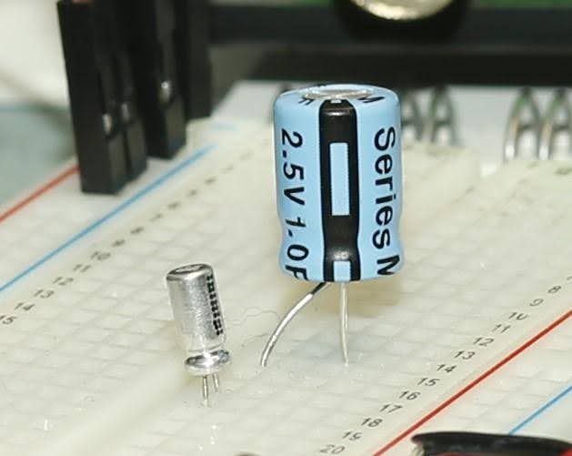
Figure 3. From LEFT to RIGHT, 0.35 mAh LTO rechargeable battery with a 1 F EDLC.
Charge storage devices are often compared with respect to the density of the energy stored, a function of the physical volume of the material. The plot in Figure 4 compares the load voltage of three types of rechargeable storage devices with comparable size for the same constant discharge current. For a load of electrical circuits that require a regulated voltage above a certain level for proper operation, a stable load voltage over time is preferable.
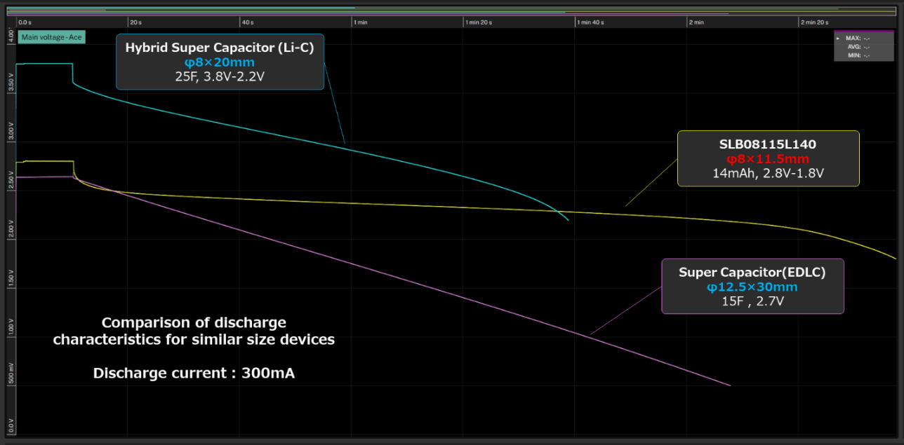
Figure 4. Discharge characteristics over time for charge storage devices of comparable physical size. The plot shows load voltage of a 25 F LIC (blue), 4 mAh LTO (yellow) and 15F EDLC (violet). Plot courtesy of Nichicon Corp.
Recharging
We would be remiss if we didn’t mention that according to the vendor, LTO is a lithium based technology that does not necessarily require a sophisticated Battery Management System (BMS) in order to charge quickly and safely when compared to other lithium based technologies. This characteristic supports frequent charge and discharge cycles required as an auxiliary energy supply.
LTO technology can also handle high charge currents up to 20 C4, charging within minutes. Similarly, an EDLC supercapacitor can be charged with a time constant determined by the capacitor value and the charge current. Both EDLC and LTO technologies can be charged with current as low as 0.01 C, a feature attractive for use with EH technology.
A comparison of the specifications for a selection of small capacity energy storage products are tabulated in Table 1.

Table 1. Specifications for a selection of small capacity storage devices.
PV System Testing
A test fixture was constructed to compare PV panels and energy storage devices for the wireless sensor load described in Figure 1.

Some key questions that we are interested in getting answers to are:
- Will the PV sustain sensor operation of a single TX cycle per day with typical indoor lighting energy (assumed 200 lux)?
- What is the minimum data transmission interval that these light levels will support?
- What time duration of sensor operation will be supported by the charge storage device once light energy is removed, such as during an offshift?
- If the storage discharges, is there enough energy to recharge storage when the lights turn back on (with no sensor load)?
- And once the storage voltage is sufficiently recharged to restart the sensor operation, will the storage device deliver the power typically required by the in-rush current experienced at start up?
The first things to consider is the PV power output, which is a function of both panel area, the number of cells configured in series and the energy conversion efficiency. The load voltage required of a primary cell replacement in this application is 3.0 V. Our initial choice is a relatively small and low cost PV from the Powerfilm portfolio, with rated MPP5 power output at both 200 lux and 1000 lux is summarized in Table 2.
| INP2.4-10x94T | Area (cm2) |
Voc (V) |
MPP voltage (V) |
MPP current (µA) |
MPP Power (μW) |
| 200 Lux | 9.4 | 2.4 | 1.6 | 21 | 33 |
| 1000 Lux | 9.4 | 2.7 | 2.1 | 105 | 219 |
Table 2. Key specifications for the PV panel tested.
To manage this range of power output, delivering safe voltages to both storage devices as well as load circuitry, we need to consider the features and functions of the PMIC. Condition Monitoring sensors that we have evaluated use a 3.0 V to 3.6 V primary cell battery6. Both the EDLC and LTO charge storage devices generally have a 2.4 V to 2.7 V maximum, so we’ll choose the PMIC that will boost the load voltage to the full 3.0 V as a replacement for the battery while protecting the charge voltage range seen by the storage devices. For the widest range of potential load voltages and tightest tolerances around 3.0 V as well as flexibility in the monitored voltages of the storage element the e-peas AEM10330 was recommended.
The PMIC can be configured to maintain a voltage to the load of 3.15 V to 3.34 V. It will cold start with 0.275 V, and turn voltage to the load on and off when the voltage on the storage device reaches configured values, selected for each storage device (Table 2).
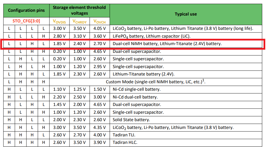
Table 3. Preset storage element threshold voltage levels for the AEM10330 can be configured with the register settings shown below. Image credit: e-peas Semiconductors.
The load for the IIoT vibration sensor current consumption was profiled in Figure 2. In this application, the data transmission consumes an average 2.5 mA for 6.6 s, but since the user configuration for the application requires measurement only one to three times per day, the total energy consumed is dominated by Sleep mode. At room temperature, this mode consumes an average current of 4.5 µA, or about 1.35 Joules of energy per day.
We need enough excess energy generated to charge an EDLC or LTO battery as backup should the facility lose ambient light for a period of time, trading off the cost of capacity with the desired number of days (or transmissions) margin for the sake of uninterrupted and maintenance free operation.
Maintaining a Charge
We tested a selection of energy storage devices, 0.8 mAh to 14 mAh LTO batteries, and 0.2 F to 15 F EDLC supercapacitors. Each was fully charged with an external source to 2.4 V before inserting into the circuit for testing. The PMIC storage voltage thresholds were configured identically for both devices, despite the differences in cutoff (minimum) charge voltages, that is 1.85 V over-discharge, 2.3 V charge-ready and 2.6 V over-charge.
Once the charged storage devices were inserted into the circuit, the sensor was run with a single transmission followed by Advertise pulses (2 s interval) while monitoring the stored voltage. The light energy was modulated, if necessary, above 200 lux until the stored voltage steadily increased at an ‘observable’ rate and full charge was reached and maintained. Then the light was removed and time to shutdown measured as the stored energy was consumed by the sensor.
Results
The 0.8 mAh LTO supported the initial sensor power up and transmission, followed by Advertise pulses every 2 s while charging with approximately 300 lux of light. After the light was removed, the storage over-discharge voltage (1.85 V) was reached after 2 h 20 m.
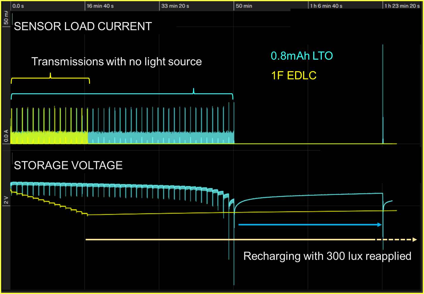
Figure 5. The current consumption profile of the wireless sensor once the LTO storage element is maintaining near a full charge and the light source is removed, resulting in steadily decreasing charge on the battery until the over-discharge threshold is reached and the load voltage is disconnected by the PMIC controller.
Performing the same test with a selection of EDLC capacitors, it was found that a 1 F EDLC could not maintain a charge under load with this light level. Increasing capacitance to 2 F and even 15 F EDLCs (all different brands) did little better in low light conditions. This result seems to affirm the view that although capacitors are valuable devices for delivering short term power (decoupling power sources from high current pulses), they are not as effective as batteries at delivering a steady supply of energy longer term. This characteristic however makes an EDLC a desirable companion to a battery for the purposes of providing short term power. This both enables lower capacity battery to be used if desired and as literature suggests, can help prolong the life of a lithium based rechargeable cell7.
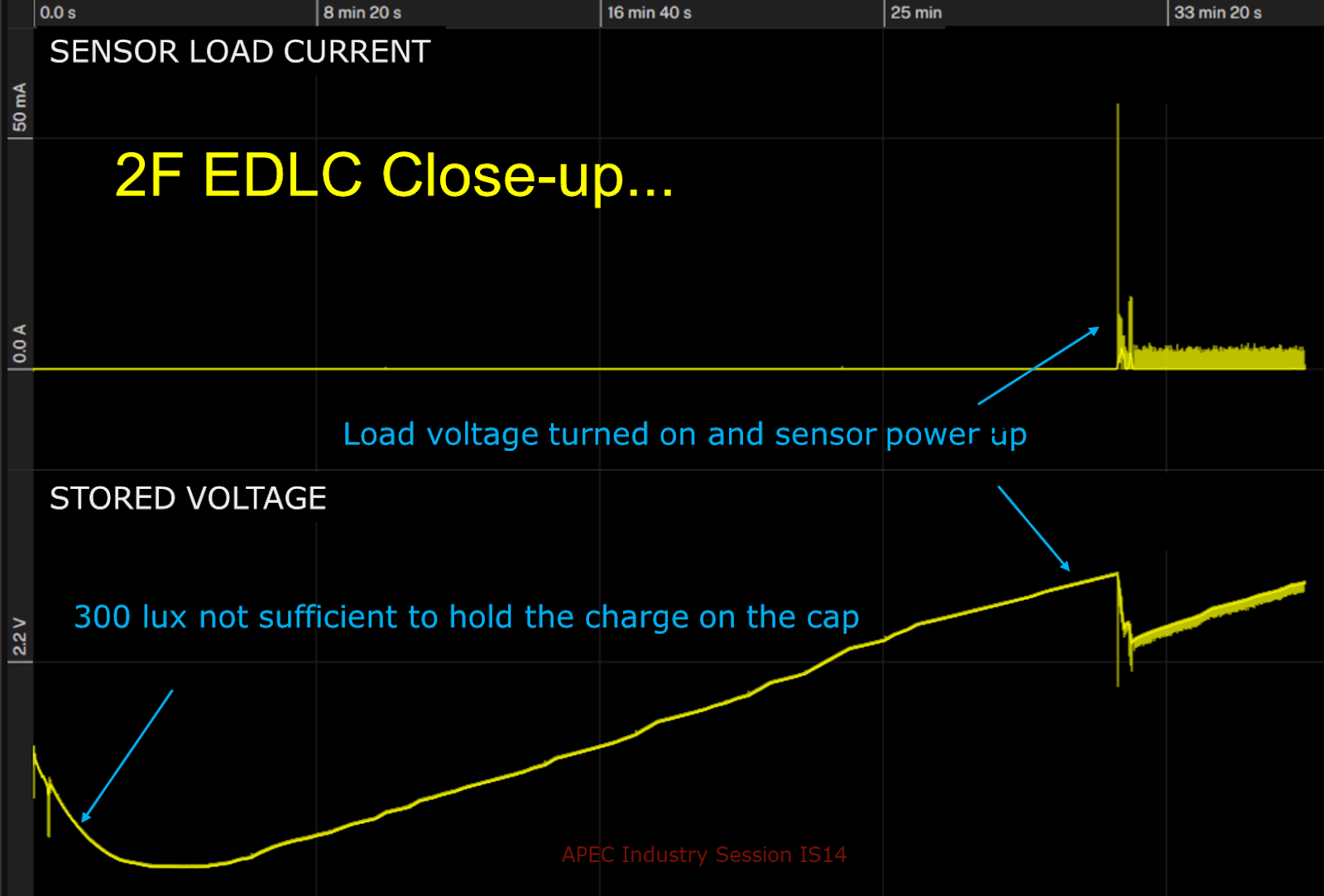
Figure 6. PV charge applied to a 2 F EDLC demonstrates that 300 lux was not sufficient to charge the capacitor. On the positive side, once charged enough to turn on the load voltage, the capacitor provided the high power associated with the current pulses associated with the sensor start-up, enabling the sensor to resume transmitting.
As we have little control over the sensor start-up configuration and hence the high current draw upon power up, we can only try to compensate with our choice of storage components. Since the EDLC does a better job filtering the start up current pulse, providing the burst of short term power as needed, one potential solution is to select the LTO capacity for the operation duration during lights out as required by the application, then add the smallest capacitor possible to provide start up power should the system over discharge under unforeseen conditions.
It turns out that a larger capacity LTO battery also supports sensor restart with virtually no impact on solution size but at some increase in cost, which may be easily justified by the additional capacity supporting longer duration operation when there is no power available from the PV.
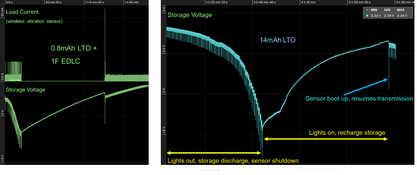
Figure 7. Testing the system with both LTO and EDLC in parallel (LEFT) leverages the strength of both technologies, enabling both many transmissions when light energy is removed as well as supporting sensor restart when sufficient recharge is achieved. That said, a higher capacity LTO will also support restart (RIGHT) while providing much more capacity for operation duration when the lights are out.
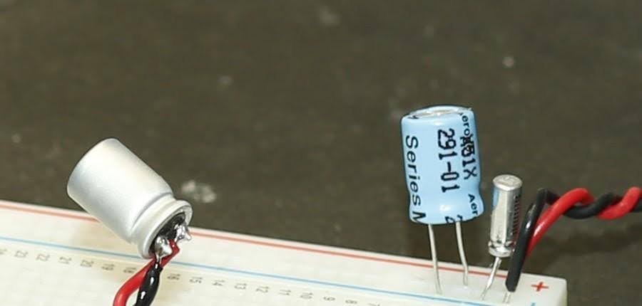
Figure 8. A comparison of the physical size of the storage solutions – the 14 mAh LTO on the LEFT, and the 1 F EDLC with 0.8mAh LTO on the RIGHT.
Discussion
PMICs are complicated electronic functions and tuning for maximum efficiency of the power transfers takes some experience given the dependencies on conditions, so there is no doubt some room for improvement regarding the choice of configuration made in this study and consultation with the vendor is always advised. The choices of storage voltage thresholds is technology dependent, and attention should be paid to the voltage drop on the storage device for any given load, such that the over-discharge voltage is not reached prematurely.
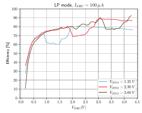
Figure 9. The 2-cell PV panel (Vsrc) output must be boosted in this case to charge either EDLC or LTO storage device, resulting in efficiency of 70% to 80%. A higher PV output will boost efficiency, as much as 90% for storage voltage of 2.4 V. Image credit: e-peas Semiconductor.
With infrequent data transmission, the sensor Sleep state will dominate the power budget, as discussed earlier. Environmental variables can have a big impact on electronics leakage current, generally increasing with temperature. For the wireless sensor tested, at 50 C the Sleep current rises from nominal 4.5 µA to 10.5 µA (average), and to 30 µA at 70 °C – a nearly 7-fold increase in the load energy. There may be little choice in this case but to accept the increased space and cost of a larger area PV, larger energy storage capacity or both to achieve similar results.
Comparing the relative merits of the technology combination to primary batteries commonly used in wireless sensors, we are also concerned of course with any additional BOM cost, operating cost and impact of expanding the form factor of a solution.
Comparing total costs of ownership has to include many assumptions such as how often the Primary batteries have to be replaced, and the replacement purchase cost8. For a 1,000 mAh battery with an estimated life of three to four years operating life under these conditions, we might assume that the battery would be replaced at least once or twice over the lifetime of the wireless sensor, for a total of two to three batteries installed9. A back-of-the-envelope calculation of BOM costs are compared in the table below.
Note that we have not tried to include labor costs of battery replacement, which might add 8% to 10% to the deployed system cost10.

Table 4. Comparison of the BOM cost of maintenance free power versus three changes of low cost non-rechargeable primary cell.
In terms of energy density (energy per volume), it’s hard to beat the LTO battery form factor. For a vibration sensor, the primary cell is often a large capacity Lithium based battery technology. See Figure 9 for examples found in commercially available wireless vibration sensors today, compared to the LTO and EDLC devices tested. The relatively small LTO package may enable some applications with smaller enclosures. In terms of mechanical design of a vibration sensor, the much reduced mass will have less impact on the vibration measurement due to mass loading as well as minimize the potential vibration of the battery holder to distort the measurements.
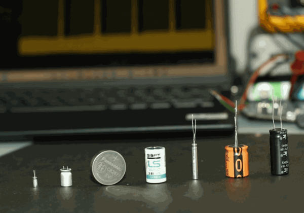
Figure 10. Energy storage devices compared to primary cells found in commercially available wireless vibration sensors today. (LEFT to RIGHT: Nichicon 0.8 mAh and 14 mAh LTO batteries, Panasonic CR2477 1,000 mAh 3.0 V Li-Ion, Saft LS14250 1,000 mAh 3.6 V Li-SOCl2 and 4 mAh LTO batteries, 20F 3 V and 15 F 2.7 V EDLCs.
There are too many variables from design, technology and environmental factors to take this analysis ‘to the bank’, but from this exploratory study it appears that rechargeable energy storage may enable self-sustaining, low duty cycle IIoT applications when paired with EH technology such as PV panels, justifying the increased BOM in terms of total cost of ownership.
The challenge is choosing the right combination of technologies, then tuning and testing the complete system for the specific application.
About the Author

Ed Spence is the Founder and Managing Director of The Machine Instrumentation Group, representing a network of consulting and contract engineering service providers helping clients define and develop new sensors for machine health instrumentation.
Ed has published or presented on subjects related to CBM / PdM on numerous occasions, maintaining an ongoing dialogue with the PdM eco-system regarding technology trends on subjects such as MEMS accelerometers, wireless sensor networks (IIoT) and data engineering for Predictive Maintenance.
1 The amount is not often specified on vendor datasheets for either EDLC or batteries. Nominal amounts of self-discharge vary by technology, but can apparently be as high as several % of nominal capacity per year for lithium batteries to 1.8% per day for EDLC. See “Self-discharge in supercapacitors: Causes, effects and therapies: An overview”, Wu and Holze, Electrochem. Energy Technol. 2021; 7:1–37
2 A Farad is the equivalent of moving 1 Coulomb of charge such that 1 V of potential is stored across the capacitor plates.
3 The cutoff voltage differs for the two technologies, complicating energy storage comparisons. Nominal cutoff for LTO is 1.85 V before impairment of battery capacity can occur with overdischarge. EDLC can be almost completely discharged but in practice the PMIC will shut off power to the load as storage energy is discharged.
4 ‘C’ corresponds to the ratio of charge/discharge current to battery capacity. 1 C is the current value at which the battery state changes from fully charged to fully discharged in 1 hour. 2 C is the current value at which the battery is fully discharged in 0.5 hours.
5 Maximum Power Point. The PMIC contains algorithms that maintain source power tracking and power conversion at MPP.
6 The battery voltage is not to be confused with the operating voltage supply of the sensor circuit. We assume that battery voltage is to be smoothed out internal to the sensor with an integrated low output impedance Low Drop Out regulator, or LDO, losing about 0.6 V to 0.7 V.
7 Using Supercapacitors to Improve Battery Performance, Smith et al, IEEE Annual Power Electronics Specialists Conference, February 2002
8 Unit cost of primary batteries for replacement is certainly much higher than the Bulk orders placed by OEMs when they mass manufacture the equipment. Storing primary batteries in volume raises issues with self-discharge.
9 Some industry observers speculate that as wireless sensor costs decline, in the future it will be more economical simply to replace the entire sensor with an updated generation.
10 Based on data from Allied Reliability, as cited earlier.